

For the Smart Cities exhibition in Leeds in a couple of weeks, we’ve been building a physical representation of an agent based simulation. Hex Bug Spiders are relatively cheap hexapod robots that are controlled via an infra-red transmitter which has an A or B code so that you can control two simultaneously. The way it walks is referred to as the Jamius walking mechanism after its inventor (see: http://www.youtube.com/watch?v=is7x_atNl94 ).
After taking the Hex Bug apart the construction is actually really good for a cheap toy. Both the hand held transmitter and the receiver in the robot are based around the AT8EB one chip microcontroller (Alpha Microelectronics Corp), with the robot itself also containing an ST1155A H Bridge driver. I’ve seen a lot of blog posts about hacking these spiders, but after trying to modify the robot’s control PCB to attach wires to the H Bridge driver directly (as in this blog post: http://www.instructables.com/id/Arduino-Controlled-Hexbug-Spider/), I’ve decided that it’s easier to replace all the electronics rather than hack the surface mount board. Out of the three spiders that I have, I’ve left two robots untouched while the third one has been disassembled. The logic behind this is to modify the IR transmitter and control two via an Arduino attached to a computer, while adding a ZigBee radio to the third for wireless control.
After examining the transmitter PCB, I noticed that there are exposed test points which can be used to attach wires for the forward, backward, left and right switches. I then discovered the following blog post doing almost exactly the same thing:
The following image shows the location of the test points on the front of the transmitter board:
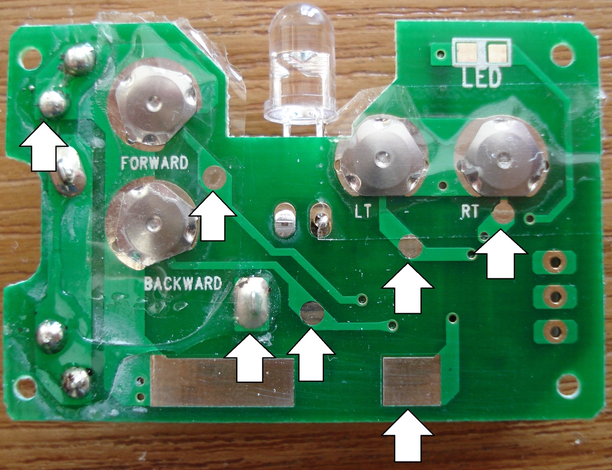
The four test points for the forward, backward, left and right buttons are exposed, so it’s easy to solder on to them. I did have to very carefully remove some of the tape covering the button clickers first though. The A/B switch is very easy to solder to, but the + and – terminals from the battery are covered in hot melt glue which was very difficult to cut away. Then I had seven wires attached to the PCB which I routed through the A/B switch hole on the front case and re-assembled the transmitter. Reading from left to right, the white arrows identify the functions as follows: GND, Forward, +3.3V, Backward, (A/B code bottom with left above it), Right.
I have seen people connect Arduinos directly to the inputs of these transmitters, but, as I wasn’t happy connecting the 5v logic of the Arduino to the 3.3v logic of the AM8EB microprocessor, I used potential dividers on all the inputs. It’s never a good idea in microelectronics to have an input pin higher than Vss even if there are protection Zeners on the inputs.
The schematic of the final circuit is as follows:
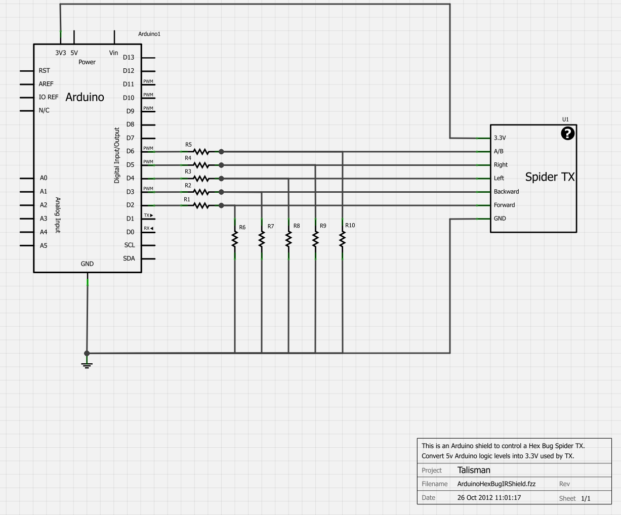
(R1 to R5 are all 10K while R6 to R10 are all 15K. Apologies for the non-standard electronic symbols)
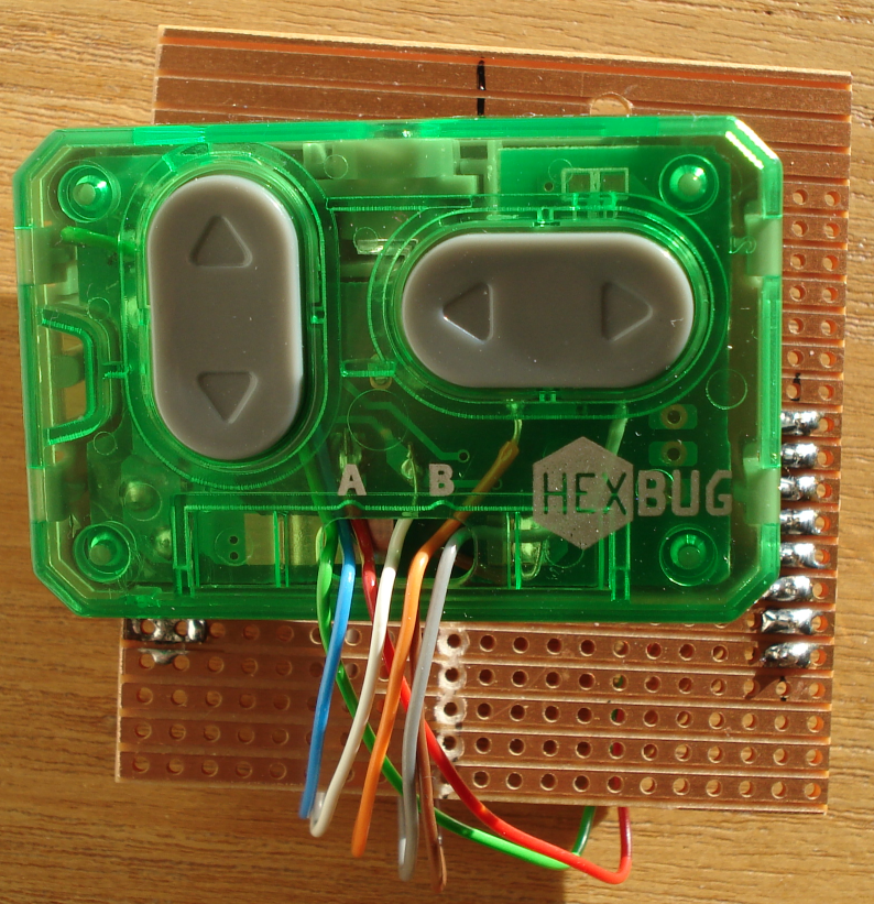
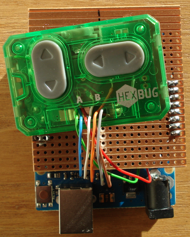
I have built this into an Arduino shield with the modified transmitter stuck onto the strip board using hot melt glue. This allows me to control two spiders via an Arduino connected via USB to a laptop. The laptop is running a Java program which uses the USB connection as a serial port to send single character commands to the Arduino which set the robot state as forward, backward, rotate left, rotate right or stop for two spiders (via the A/B code).

What I’ve found is that there needs to be about a 1 second delay after bringing up the serial port before you start sending commands to the robots, otherwise you lose the commands. While this does work to control two spiders from one transmitter using multiplexing on the Arduino to flip between the A and B codes, I think you really need two HexBug Arduino shields for it to work. By trial and error I found that holding the TX pins in spider A’s state for 80 ms, followed by the same for spider B, gave fairly reliable control of both simultaneously. Now that the project has progressed beyond the initial stages and we’re using a webcam to position the spider, this A/B code multiplexing is causing a lot of problems. The next phase involves getting the spider to follow a coloured marker and the only way I could get this to work reliably was to disable the A/B code multiplexing on the Arduino.